ROLE OF FIXURES IN ULTRASONIC PLASTIC WELDING
The use of CAD/CAM technology has greatly improved the manufacturing of contoured fixtures to support the part during ultrasonic assembly. Exact mirror replicas of the part can be created to provide excellent support to the part. Due to complex contours seen on many parts, it is recommended that the horn and fixture be purchased as a set, so proper alignment is achieved between the two. The fixture used for ultrasonic assembly is often overlooked, but usually very critical to the success of the application.
The use of a fixture that is not properly designed will usually result in very poor welds or no weld at all. Typically you want the fixture to support the part half to be welded that has the deepest draw. The horn will contact the other part to be assembled, so that the distance from the horn contact surface to the weld joint is minimized. The primary purpose of the fixture is to hold the part secure, in position and in alignment to the ultrasonic horn that will descend upon the assembly. It is important to support the bottom of the part to prevent it from deflecting under the pressure applied by the ultrasonic welder. If the part does not fit correctly, alignment can be impacted and energy that is needed for the weld can be dissipated into locations not necessary for the weld. A sloppy fit can actually create a condition in which the parts vibrate in unison instead out of phase with each other. It is preferred that the part in the fixture be held sufficiently to allow the mating piece to vibrate against the fixtured part and create a melt flow. If the parts vibrate in unison during ultrasonic vibration, the frictional activity is decreased resulting in less melt flow.
Many different types of materials have been used to build fixtures for ultrasonic assembly including plastics, stainless steel, tool steel, aluminum, cork, poured urethane and silicone rubber. All of these can play a role depending upon customer’s needs, but the most common fixtures include aluminum, steel and poured urethane. Poured urethane fixtures are frequently used for supporting rigid amorphous plastic parts. Urethane fixtures are especially advantageous for providing good support with rigid parts and eliminating or reducing part marking that can occur during ultrasonic assembly. Urethane fixtures have also been used successfully as a part support for insertion and staking applications. Urethane fixtures have been used successfully for insertion applications with 8-32 or smaller inserts and staking applications with boss diameters less than 1/8 of an inch. Historically, urethane pours were not uniform and often used too much urethane in areas for supporting the part. Due to the resiliency of urethane material, this inconsistency of the poured urethane would result in varying support at different locations around the part. The advent of new thin poured urethane fixtures provides good consistent support and a resistance to burning that was seen with the thicker poured urethane fixtures that were used in previous generations of ultrasonic welding. The use of the thinner poured urethane fixtures can be advantageous to welding, reduce part marking and provide good support to the part allowing for good transfer of ultrasonic energy to the part and not the fixture. The most commonly used nest material is aluminum. Aluminum provides good rigid support and can easily be reshaped if the plastic parts come in oversized. It is used for both crystalline and amorphous parts. Aluminum is almost always the material of choice for supporting parts made of crystalline type plastic materials. Aluminum fixtures may need to be hard coated if the plastic material includes abrasive fibers, but the material is generally clear anodized or chrome plated to prevent part marking. Part marking is a real concern with a rigid aluminum nest, particularly if the part does not fit the nest well. If the contours don’t match, the vibratory energy can result in the rigid fixture marking the plastic part creating an unsightly scar. Steel is also used as a fixture choice for ultrasonic assembly. It is often chosen for its improved wear characteristics, particularly when welding highly abrasive materials. It is also selected for use as anvil fixturing to provide knurling and various stitch patterns for textile weld and slitting applications. No coating is required if the material is stainless, but black oxide coating is frequently used for other tools steels.
The deciding choice for fixture materials usually comes from the type of support required and the type of weld joint used. The fixture usually supports the lower part up to the parting line to prevent part marking during the ultrasonic assembly process. If the part has a deep draw it is probably advantageous to use aluminum material to improve loading of the part into the nest and unloading of the part out of the nest. On crystalline material applications, a joint called a shear joint is frequently employed which causes the part to expand at the weld joint as the material melts. With this type of joint, you would want to make sure the fixture material is very rigid to suppress deflection and make sure the melt occurs along the vertical wall of the shear joint. Due to the resiliency of urethane material, it would not be a good material choice for a shear joint welding type of application. When a part is welded using an energy director joint where there is no force against the outside wall, most of the support is needed on the part in the area under the energy director. With the energy director joint the most common choices are aluminum, stainless steel and poured urethane.
The fixture material choice will also affect how the plastic material flows at the joint interface. A soft resilient type of material will create a different flow rate than a rigid metal nest. Different fixture materials will create various frictional reactions at the weld joint. An experienced ultrasonic tool maker can assist with choosing the appropriate fixture material. Most of the time they will be right based upon their application experience and exposure to the broad choice of plastic material choices used to manufacture plastic products. Fortunately, if they select wrong it is rarely a life altering event.
Most fixtures include a slotted aluminum subplate for mounting to a welder base or automation system. The slotted subplate allows for ease of alignment between the part and the ultrasonic horn. Many fixtures will incorporate leveling features on the aluminum subplate to adjust the nest if the fixture in not parallel to the machine and the ultrasonic horn.
Just about any type of attachment can be added to an ultrasonic fixture to improve alignment, enhance part loading and unloading, eject the part, clamp parts, provide slides to move the part or the fixture, etc. Servo and pneumatic drive motion control systems have also been used as fixture attachment devices to lift the part to a stationary vibrating ultrasonic horn. Common used fixture attachments include the use of clamps and slides. A clamp is often used to provide support to the part, but allow a split fixture to open wide for part loading. This clamp approach allows the fixture to provide excellent support at the joint, but still open up for part loading. This fixture clamping approach is often necessary due to limited stroke capacity of the ultrasonic weld machine. Slides are also incorporated into fixture designs to move the part into a position out from under the ultrasonic horn to allow for part loading. Slides are also used for welding at different locations on the part, to move a fixture component into position for improved support and to scan along a weld seam. Slides have been used to move a part along an X-Y axis to aid in installation of multiple inserts or to allow the horn to stake posts at multiple locations. With the use of slides one finds other fixture attachments like stops and detents to control the motion position. The use of clamps and slides can be activated manually or automatically depending upon requirements for volume, ease of use and cost considerations. Mechanical part ejection attachments are often added to fixtures to enhance part removal after the ultrasonic welding process. This eject feature is generally required if there is a deep draw to the part or the part imbeds itself into the nest during the assembly process. The mechanical eject attachment components can be as simple as a manual lever lift or a little more complex like a lift driven by a pneumatic cylinder. Smart fixtures with plc controls have been used as a fixture attachment to provide sensors to ensure part placement before the weld cycle and to activate automatic part ejection after the weld cycle. It is feasible to envision that these smart fixtures could also incorporate part loading.
Customers that need rapid tool change are constantly requesting quick change fixtures. For quick change tooling, the use of dowel pins and bushings are commonly found fixture attachments. Coupled with quick tool change features for the ultrasonic transducer, booster and horn assembly, the end user has the capability to change jobs much faster providing a substantial reduction in setup time.
Dukane Advances the Ultrasonic Delivery System
Ultrasonic welding has been in existence as an assembly process for over 40 years. As a method of bonding plastics, it has become one of the most accepted processes because it is clean, energy efficient and fast.
The birth of ultrasonic welding was discovered quite by accident, as many modern marvels are similarly invented. In the early years of the technology, the energy was applied to the plastic part by an operator who would manually pull the lever arm of an arbor press, which held an ultrasonic transducer and horn. In those days, the pressure would vary during the process and the amplitude would droop tremendously as the load was applied to the material. The process control was crude, but an industry had been launched.
During the late 1960’s and early 1970’s, ultrasonic machines were produced with pneumatic delivery systems and manufacturers called these components, presses or actuators. As a means for delivering the converter and the horn to the plastic, these systems were significantly advanced when compared to the previous hand controlled choice. In the 1980’s and 1990’s new products were produced that controlled the amount of energy delivered to the plastic. Ultrasonic welding machines were developed allowing welding by distance. Other significant electronic advances were made to the power supplies to control amplitude and stay current with the digital revolution. However, the delivery system for bringing the vibrating horn to the plastic has continued to be the standard actuator or press comprised of pneumatic components.
Back in the mid 90’s I predicted that I would be surprised if by the year 2000 manufacturers of ultrasonic plastic welding equipment had not incorporated the servo controlled technology into their standard product line. It just made sense. These innovative machine motion control systems provide the ability to control and profile force with the acceleration and deceleration features embellishing the welding process. I thought that servo controlled ultrasonic systems would become as common place as servo controlled injection molding machines.
Wow was I way too early with my prediction. However, one manufacturer has finally seen the light. Dukane has developed a new delivery system that looks like it could provide users a degree of control not previously realized in the industry. I am sure it is expensive and not meant for all applications, but for those companies looking for precise control of the process it is probably worth investigating.
Gary Clodfelter
Plastic Assembly Technologies, Inc.
Aluminum & Titanium Ultrasonic Boosters
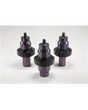
Plastic Assembly Technologies has introduced a new line of aluminum and titanium rigid mount ultrasonic boosters without spanner wrench holes. Ultrasonic boosters without spanner wrench holes result in a reduction of stress location points on the booster and provide for boosters that are less prone to fail. Additionally, these boosters are all of the same length, allowing the user to change the amplitude of the converter, booster and horn assembly without affecting the length of the assembly. Therefore, the amplitude can be mechanically changed without requiring significant adjustment in the welder setup. The rigid mount design reduces deflection during the ultrasonic welding process providing for less potential variation during welding. The boosters are priced to reflect the cost of conventional boosters, but provide a host of additional benefits. The ratios of gain changes available are 1:1, 1.5:1, 2.0:1 and 2.5:1. The boosters are designed to fit in Branson or Dukane ultrasonic welders using 3.250″ diameter ring mounts. Plastic Assembly Technologies has developed a stack vise to ease the changeover.
Full Wave Ultrasonic Horn Resolves Problem
Full wave ultrasonic horns are known to have resolved horn failure issues when half wave designs have proven unsuccessful. Most ultrasonic horns are manufactured based upon a half wave design. The half wave design is used to reduce material and machining costs. However, there are applications and specific design situations that warrant the use of a full wave ultrasonic horn.
One example that justifies consideration of a full wave ultrasonic horn is an application that requires a deep pocket in the working face of the tool. When a deep center pocket is placed in a half wave ultrasonic horn, the result is usually more stress on the tool than when the pocket is placed in a full wave ultrasonic tool. This is because deep pockets in half wave horns can result in secondary frequencies, indicating that there are undesirable flexural or bending motions in the tool. These flexural or bending directions of vibration are not in the desired axial direction of motion and can result in increased stress, which can cause a horn to fail prematurely.
Horns are designed to resonate in an axial mode of direction. Deep pockets in a half wave horn are so close to the nodal area of the horn that the axial mode is contaminated by the proximity of the pocket to the back mass of the tool. When an ultrasonic horn is driven at ultrasonic frequencies, it is driven from the center element of the tool. When a half wave tool has a deep pocket in the center element, the horn has to do more work to drive the center element at the desired frequency and this results in undesirable bending or flexural motions. By making a full wave tool, solid mass is added to the center element and this additional mass pushes the center element with more force. This additional mass driver results in a purer direction of motion on the tool and drives the tool more uniformly in the desired axial motion, reducing the flexural motion and stress.
Plastic Assembly Technologies has solutions to your ultrasonic horn problems. Contact Us
CompuWeld© Program for Ultrasonic Welding

CompuWeld© Software is used for data acquisition with Branson 900 and 2000 series ultrasonic welders for monitoring weld data and providing real time SPC of the critical weld data from the ultrasonic welding process. CompuWeld© SPC or Statistical Process Control involves collecting data from a welder for the purpose of monitoring the process through the use of statistical tools, such as XBar and RBar control charts. Analyzing the output data is done to maintain control of the process and to improve performance of the process. In ultrasonic plastic assembly, the information available about the welding process comes in the form of data about WELD TIME, WELD ENERGY, PEAK POWER, WELD COLLAPSE DISTANCE, TOTAL COLLAPSE DISTANCE AND ABSOLUTE DISTANCE OR FINAL POSITION.
WELD TIME is the duration that ultrasonic energy is on during the weld cycle. ENERGY is the total value of the watts used during the cycle multiplied by the actual time used during the cycle. PEAK POWER is the largest percentage of watts used at a single point in time during the cycle. WELD COLLAPSE is the amount of distance the actuator traveled after the trigger switch was activated and before the hold time. TOTAL COLLAPSE is the amount of distance the actuator traveled after the trigger switch was activated and after the hold time. ABSOLUTE DISTANCE or FINAL POSITION is the total amount of distance traveled by the actuator after leaving the upper limit switch. By monitoring these process variables, we hope to minimize unwanted causes of variation and improve control of the ultrasonic welding process.
There are two types of variation evident in all processes. Natural or random variation and variation caused by special or assignable causes. A process is said to statistically be in control when the only source of variation is coming from natural or random causes. But as Deming said, “a state of statistical control is not a natural state for a manufacturing process. It is instead an achievement, arrived at by elimination, one by one, by determined effort, of special causes of excessive variation.” Types of special causes that can be found in the use of ultrasonic equipment include variation evident in differences in equipment, tooling, setup, operators, material, molding conditions and the environment. In order to use the statistical tools available in “CompuWeld© 2000″ for monitoring a stable process, the welding process must first be brought into statistical control by eliminating causes of variation created by special or assignable causes.
On the CompuWeld© 2000 run view screen, one can see (6) XBar, RBar charts on the screen at one time. The XBar chart is drawn with the XBar above the RBar chart. The values of XBar and RBar are displayed on the vertical scale and the sequence of subgroups are displayed through time on the horizontal scale. The variable being monitored is shown on the top left corner of the XBar chart. XDouble Bar and RBar are shown with dotted lines running horizontally. Control limits are shown with solid lines running horizontally. The last subgroup average measurement and the last subgroup range or variation is shown on the bottom left corner below the RBar chart. The process capability measurements known as the CP ratio and CPK are shown on the bottom right hand corner below the RBar chart. The picture above is illustrative of the data available from the Compuweld© software.
Ultrasonically Bonded Swimsuit
The Speedo LZR Racer swimsuit was used by gold medalists at the olympic games and was bonded with ultrasonic welding to reduce drag. Ultrasonic bonding helped provide the LZR Racer swimsuit with the necessary competitive edge.
Routine Ultrasonic Plastic Welder Maintenance
The routine maintenance items for an ultrasonic welder are simple unless there is a machine failure. The following are recommended maintenance procedures.
1. Make sure that you have a Mylar washer between the converter and booster and between the booster and horn. We recommend replacing these washers every 6 months. A bag of (10) Mylar washers can be purchased for $12.00 from Plastic Assembly Technologies, Inc. at www.patsonics.com.
The Plastic Assembly Technologies part numbers are as follows:
· MW-12 for a bag of (10) Mylar washers for use on ultrasonic horns and boosters with ½-20 studs
· MW-38 for a bag of (10) washers for use on ultrasonic horns and boosters with 3/8-24 studs.
2. When disassembling the stack (ultrasonic converter, booster & horn) for replacing the Mylar washers, check the studs to make sure they are properly torqued. The stud torque is 290 inch/lb for 3/8-24 studs and 450 inch/lb for ½-20 studs. When reassembling the stack, the torque specification of the converter to the booster and the horn to the booster is 220 inch/lb.
3. Drain the air filter as required if it has collected moisture. Dry air is recommended as air with moisture will eventually impact the functionality of the pneumatic system.
4. Once a year or more in dirty environments, use light air pressure or vacuum to clean the inside of the power supply. Make sure the power is disconnected before following this procedure.
Ultrasonic Weld Joint & Part Design
Energy Director Design
While it is possible to ultrasonically weld plastic materials without specific joint design details, the weld process is greatly enhanced by adding proven features that aid in the process. For example, without a means of alignment built into the joint it is impossible to predict where the parts will be positioned after welding. This is due to the nature of the vibratory process created by ultrasonic welding. This means of alignment is accomplished through the use of step joints, tongue and groove joints, pins and sockets, raised walls, ribs or other features that are used to keep the vibratory process under control to maintain the desired alignment of the parts after welding.

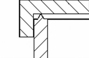

A feature that is shown in these joint alignment pictures is the molded-in triangular shape of material called an energy director. This molded-in triangular ridge of plastic is very effective at reducing the cycle time to achieve a weld and in compensating for non-uniform wall surfaces. The energy director design has been used for years as a means of focusing the energy to improve weld strength and reduce cycle time. The energy director is typically placed only on one half of the part and runs along the surface to be welded. Without this energy director the weld quality would be suspect for many applications. The peak of the energy director should be sharp with a triangular shape formed from a 60º or 90º included angle. A 60º angle is generally used with crystalline materials and a 90º is used with amorphous materials. Material types by polymer structure are illustrated below:

|
Amorphous Resins 90º Angle |
|
Semi-Crystalline Resins 60º Angle |
|
ABS-Acrylonitrile Butadiene Styrene |
|
PA- Polyamide (Nylon) |
|
ABS/PC-ABS/Polycarbonate |
|
PBT-Polybutylene terephthalate (Polyester) |
|
ASA-Acrylonitrile Styrene |
|
PE-Polyethylene |
|
Acetate |
PEEK-polyetheretherketone |
|
|
PC-Polycarbonate |
PET-Polyethylene terephthalate (Polyester) |
|
|
PEI-Polyetherimide |
PMP-Polymethylpentene |
|
|
PES-Polyethersulfone |
POM- Polyacetal |
|
|
PMMA-Acrylic |
PP-Polypropylene |
|
|
PPO-Polyphenylene Oxide |
PPS-Polyphenylene sulfide |
|
|
PS-Polystyrene |
|
|
|
PSU-Polysulfone |
|
|
|
PVC-Polyvinyl Chloride (Rigid) |
|
|
|
SAN-Styrene Acrylonitrile |
|
|
|
SBC-Styrene Block Polymers |
|
|
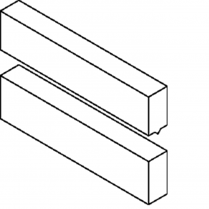 Depending upon the wall thickness and the application, the energy director typically varies in height in a range from .010 to .035 of an inch. The minimum height recommended is .010 for most amorphous materials, .020 for semi-crystalline materials and the amorphous polycarbonate material. While we’ve seen energy director heights of .060 of an inch tall, most energy directors don’t exceed .035. Using a 90º energy director design, the height of the energy director is often determined by the width of the wall where the width of the wall is divided by eight, so that we have an energy director height equal to W/8.
Without some designed in approach to controlling flash, an energy director by itself has the potential for molten material to flow beyond the wall creating flash outside the weld joint. If flash is a problem the use of step joints, tongue and groove joints, flash traps, raised walls and energy director placement have all been employed as a means of controlling the material flow.
Two types of joints commonly used to control flash and provide alignment are the step joint and the tongue and groove.
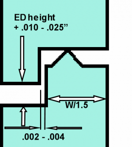

Both of these joints provide excellent flash control and the alignment necessary for a good ultrasonic weld joint design. The tongue and groove design provides the added benefit of being as an excellent reservoir for the melted material. This pooling of plastic material helps contain the material and increases the likelihood of a hermetic seal. The additional height of .010 to .025” added as a gap around the periphery of the part provides a shadow line that helps to hide variation with part tolerances and melt flow during the ultrasonic welding process. This is a feature that we highly recommend because it helps to eliminate potential flash caused by the mating perimeter surfaces touching and it becomes imperceptible to the eye when the weld melt down is not perfect.
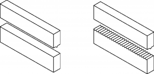
Recent advancements with the energy director design have resulted in the use of the criss-cross energy director design. Essentially, the criss-cross energy director design utilizes the standard energy director shape where a triangular shaped bead of material is molded into the plastic wall. The energy director has typically been placed only on one half of the part and runs along the surface to be welded. Although it usually doesn’t matter which of the parts to be welded incorporate the energy director, it is probably more common to find the energy director on the half that the horn contacts. With the use of the criss-cross design, additional energy directors are added to the mating part, which increases the amount of material interaction. On the mating surface opposite the perimeter energy director, a series of perpendicular energy directors are molded-in to mate with the perimeter energy director. See the illustration above.
When a hermetic seal is desired these additional energy directors should take on a saw tooth pattern with each energy director repeating from the base of the proceeding energy director. Because there are energy directors on both mating surfaces, the energy director height on each half should be reduced to prevent excessive material flash during welding. Typically, it is recommended that the criss-cross energy director height be approximately 60% of the standard design.
The criss-cross energy director joint design is particularly effective when used in combination with a tongue and groove. Because of the increased material flow with the criss-cross energy director design, it is recommended that a tongue and groove joint be used to capture the additional plastic and contain the flash.
This criss-cross design certainly increases the mold cost, but we’ve seen applications where the weld strength has far exceeded expectations and hermetic bonds have been achieved that might not have been achieved using the standard energy director on one mating surface.
Shear Joint Design
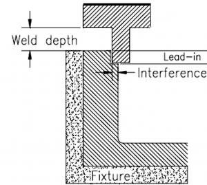
 Although the energy director design can work satisfactory for welding semi-crystalline plastic materials, there are circumstances that warrant the use of another type of joint design. When welding materials like nylon, polyacetal, polyester, polyphenylene sulfide, polypropylene or polyethylene and a hermetic seal is required, the shear joint has proven beneficial for many applications. Therefore, the shear joint is frequently used when a hermetic seal is required on semi-crystalline plastic materials.
The reason for using a shear joint relates to the way the semi-crystalline material flows when introduced to heat. These types of plastics have a very sharp melting point and once the heat is reached to create a melt flow, the material immediately becomes liquid and flows rapidly. Semi-crystalline plastics also re-solidify within a small temperature variation. When an energy director is used with semi-crystalline plastics, the molten material gets exposed to a lower temperature when outside of the melt zone and can re-solidify before the desired bond is achieved. Because the melt zone of a shear joint is held along a vertical wall, the temperature variation is reduced within this melt zone since the material is not easily exposed to the surrounding air.
The shear joint is not the answer for all applications. We recommend caution when applying the shear joint to polypropylene or polyethylene due to the lack of rigidity in these materials. The lack of stiffness with these materials often results in pushing past the shear joint instead of melting and welding the material at the joint interface. The shear joint requires high tolerance, so we also recommend caution incorporating a shear joint design on larger parts. The shear joint should not be used when a part is larger than 3 ½” in diameter or has sharp corners or unusual shapes. When you are welding semi-crystalline parts under one or more of these caution conditions, the 60º energy director should be considered. If a hermetic seal is required on a product made from semi-crystalline resins and an energy director should be used because of the material, size, shape or tolerance requirements, the use of the criss-cross energy director design has proven successful for specific applications. Reference the information above for welding semi-crystalline material with an energy director.
Machine Troubleshooting
MACHINE OVERLOADS – POWER SUPPLY, CONVERTER, BOOSTER, HORN OR OTHER FAILURE?
1. Begin by pushing the test button to see if the power supply overloads when running the converter, booster and horn in air. If the power supply overloads in air, remove the converter, booster and horn from the welder and inspect the assembly carefully. Look to see if there are visible cracks, check to see if the horn is properly torqued to the booster and if the booster is properly torqued to the converter and then check to see the interconnecting studs are properly torqued. Loose horns, boosters and studs will cause overload conditions. If the stud is loose, torque the stud to 290 in-lb for 3/8-24, 450 in-lb for 1/2-20 and 70 in-lb for 8mm stud. If the horn or the booster appears loose, tighten to these torque specifications: 220 in-lb for 20 KHz and 95 in-lb for 40 KHz. If either of these components appears cracked, contact us at 317-841-1202 or www.patsonics.com. A word of caution is in order. It is possible that you cannot visibly see a crack, but a crack does exist.
2. If everything appears to be okay in step 1, disassemble the converter, booster and horn. Make sure the mating surfaces of the converter, booster, and horn are clean. Check to see if there is a .003 thick Mylar washer between the interfaces. If so, remove the washers. (Note: if the washers were in place it is likely that the interfaces will be clean.) If the surfaces are not clean, wipe the interfaces with a soft cloth or paper towel. If the interfaces show pitting or residue buildup, they will need to be resurfaced. To resurface, remove the studs that connect the booster to the converter and the horn to the booster. Place a sheet of 400 grit emery cloth to a flat surface and pull the component with the worn surface against the emery cloth. The component should be pulled in a straight line, not in a figure 8 or other pattern, and held perpendicular to the emery cloth. You should recondition the components by pulling in one direction only and then rotating the component 120 degrees and re-stroking. It is not necessary to apply pressure as the weight of the converter, booster or horn should be sufficient to provide the needed force. This process should be repeated until most of the pitting or residue is removed and this is usually accomplished within a few rotations. Note: It may not be possible to remove all of the pitting. You don’t want to remove all of the craters if the pitting is deep because these are tuned components and too much removal of material will alter the frequency. Once you have the interfaces clean, the converter, booster and horn should be reassembled.
3. Before reassembling the converter, booster and horn, inspect the interface studs that were removed in step two above. It is possible that these studs have failed and will need to be replaced. If the studs are in good condition they can often be reused, but this is a great opportunity to replace the studs if they are available. Reinstall the studs using the specifications provided in step 1. The interfaces between the converter and the booster and the booster and the horn should be treated before reassembling. If you have Mylar washers available, this would be the preferred way of protecting the interfaces. Place one Mylar washer over the stud of the booster and one Mylar washer over the stud of the ultrasonic horn. A bag of Mylar washers can be purchased from Plastic Assembly Technologies, Inc. for $10.00. If Mylar washers are not available, you should use a small amount of silicone grease between the interfaces. Be careful not to apply the silicone grease to the mating studs. Reassemble the converter, booster and horn assembly and retest the stack for the overload condition.
This post will be updated frequently in an effort to provide you with additional information on machine troubleshooting. Please check back for more updates. Thanks for visiting.


